
Selecting the correct motor for industrial automation can be complex. This AC Gear Motor Sizing Guide provides a systematic approach to matching voltage, torque, and mounting specifications to your project needs.
Core Selection Parameters
Selecting the right AC gear motor requires confirming four primary parameters:
| Parameter Dimension | Sizing Example | Core Meaning |
|---|---|---|
| Voltage/Frequency | 3-Phase 208V/60Hz | Depends on the power supply available on-site. |
| Power | 400W | Determines the motor’s load-carrying and driving capacity. |
| Gear Ratio | 50:1 | Amplifies the base motor torque by 50 times (multiplied by the efficiency coefficient). |
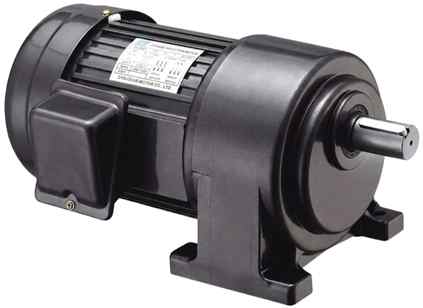
| Mounting & Dimensions | Horizontal mount, 28mm keyed round shaft, 90mm×140mm mounting holes | Determines physical assembly and mechanical compatibility. |
Voltage & Frequency: Essential Part of this AC Gear Motor Sizing Guide
Motor speed is directly related to the power supply frequency; never ignore frequency differences. Take a 2-pole motor as an example:
- 60Hz Theoretical Speed: 60s × 60Hz = 3600 rpm.
- 50Hz Theoretical Speed: 60s × 50Hz = 3000 rpm.
- Note: The actual speed of an asynchronous motor will generally be lower than the theoretical speed.
Global Common Single-Phase / Three-Phase Power Supply Reference
| Region | Single-Phase (1-Phase) | Three-Phase (3-Phase) |
|---|---|---|
| Asia / Europe / Australia (Most countries) | 220V/230V, 50Hz | 220V/230V, 50Hz 380V, 50Hz 400V, 50Hz 660V, 50Hz |
| Canada / USA | 110V/120V, 60Hz 240V, 60Hz Split-phase 120V/240V, 60Hz 277V, 60Hz | 208V, 60Hz 240V, 60Hz 415V, 60Hz 440V, 60Hz 480V, 60Hz 600V, 60Hz 220V, 60Hz few |
| Japan | 100V/110V, 60Hz | 200V 60Hz |
Power Transmission Parameters: Power, Gear Ratio & Torque
| Parameter Category | Sizing Rules & Ironclad Principles |
| 1. Power | Micro Power (10W – 60W): Compact size, suitable for light-load and space-constrained applications like small instruments and automation fixtures. |
| Medium to High Power (200W+): Strong power, suitable for heavy industry and commercial machinery like conveyors and packaging machines. | |
| ⛔ Ironclad Rule: After calculating the theoretical power, you must reserve a 1.2 to 1.5 times safety margin. Never size for full load or overload operation. | |
| 2. Gear Ratio | Calculation Formula: Motor input speed ÷ Gearbox target output speed. |
| Define the final speed range required by the equipment, and calculate the gear ratio directly backwards from the target speed. | |
| 3. Torque | Speed is inversely proportional to torque; the higher the gear ratio, the greater the final output torque. |
| ⛔ Ironclad Rule: The rated output torque on the motor nameplate must be strictly greater than the equipment’s maximum operating torque and starting torque. |
Mechanical Mounting & Output Matching Guide
You must confirm whether the physical dimensions fit your current design project or can seamlessly replace a damaged gear motor. If the shaft diameter is too large or the mounting holes do not align, installation will be impossible. The industry has standard mounting dimension specifications, such as the European IEC standard, the Chinese GB standard, and the American NEMA standard.
| Matching Item | Specifications & Notes |
| Mounting Method | Horizontal (Foot Mount): Low center of gravity, stable stress distribution, most versatile. Vertical (Flange Mount): Space-saving, suitable for vertical transmission equipment (e.g., mixers). Note: Vertical mounting requires strict confirmation of the gearbox’s oil seal rating to prevent leaks. |
| Output Shaft Type | Select the matching shaft type based on the connecting components (gears, couplings, pulleys, etc.): Round shaft (smooth), Keyed shaft, or D-cut shaft.Always verify the specific dimensions and tolerance fit of the shaft diameter to prevent slipping or assembly interference. |
Operating Environment & Additional Features
Customized selection must be made based on the actual working conditions of the equipment:
- IP Rating (Ingress Protection): Standard enclosures are sufficient for typical indoor equipment. For environments involving water exposure or high dust, strictly specify fully enclosed motors with IP55 or IP65 ratings.
- Speed Control: If the application requires frequency conversion or dynamic speed changes, choose a variable speed motor paired with a dedicated controller.
- Braking Function: For hoisting mechanisms, lifting equipment, or safety nodes requiring emergency stops upon power loss, an electromagnetic brake must be added.
Sizing Pitfalls to Avoid (Instant Dealbreakers)
Even if you carefully follow the calculation steps in an AC Gear Motor Sizing Guide, ignoring physical loads and duty cycles can lead to premature motor failure.
⛔ Ignoring Radial/Axial Loads: In addition to calculating torque, you must strictly check the lateral load on the output shaft. For instance, overly tight drive belts can easily cause shaft breakage or premature bearing failure.
⛔ Unclear Duty Cycle: You must specify whether the motor operates “24 hours continuously (S1 Duty Cycle)” or under “frequent start/stop” conditions. Frequent start/stop scenarios require upgrading the motor’s cooling rating or further increasing the power safety margin.
⛔ The Noise Blind Spot: For equipment used in medical devices or smart homes, your procurement requirements must explicitly specify “low noise / precision-milled gears.” Never use standard, high-noise industrial gearboxes for these applications.
Interactive Animation of AC Gear Motor Applications
To complement the theoretical calculations provided in this AC Gear Motor Sizing Guide, the following interactive animation demonstrates typical industrial deployment scenarios
We hope this AC Gear Motor Sizing Guide helps your project. For customized solutions, please check our homepage. Applying the principles outlined in this AC Gear Motor Sizing Guide ensures long-term reliability and efficient power transmission for your entire system.